
FAQ: Can I use ZWAVE to open and close windows?
Our ZWAVE® shade and blind motor controller (DCC-ZWAVE-12R) can be also be used to activate our window and skylight motors using our wired wall switch.
In the first article in this series, we looked at the operation of the ZWAVE interface receiver module that can act as a trigger to control various devices. In this second article we will show you how you can connect it to an interface switch to control window openers and other DC motors and devices.
You can use it with any Z WAVE hub, such as Wink, SmartThings, Vera, Homeseer, Syslink, Zipr, Xuan, Razberry Pi, Staples Connect, Fibaro, Xuan, Homelive, Isis, Nexia, etc.
The ZWAVE radio control signal is also capable of passing through walls and in most cases can reach anywhere inside a typical home. It is a true mesh network, as each module also acts as a repeater, passing control signals on to adjacent zwave modules.
This article discusses the operation of our window and skylight motors, but you could just as easily use this system to operate our motorized irrigation valves.
Z-Wave Window and Skylight Openers
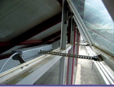 We connect the ZWAVE trigger module to our wired wall switch which controls the DC voltage and reversing polarity of the motor feed, providing open/close/stop functions for our unobtrusive chain actuators that open and close windows and skylights.
These units use an interlocking chain that emerges from the housing at a right angle as the window opens, and they are very uncluttered when the window is closed, blending into the window sill.
The actuators can also be used to push/pull anything you like, they are not limited to window and skylight applications. We've had customers use them in all kinds of different ways: raising and lowering TV sets, projectors, panel doors, etc.
The wired wall switch can also be used as a simple ZWAVE on/off switch for devices that do not require motor reversing: fans, LED light strips, irrigation valves, etc.
ZWAVE Motor Control Wiring
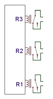 In the first ZWAVE introductory article we looked at the basic functionality of the z wave controller. Essentially it has 3 single pole, normally open relays that are operated directly by the zwave control signal.
A relay is a simple electronic switch, not much different from a regular wall light switch, except it uses magnetism (generated by a DC current flowing through a coil of wire) to close and open the contacts.
Here we have taken the schematic shown in the previous page and rotated it 90 degrees so that we can expand the diagram horizontally. You can see the 3 relay representations of R1, R2, and R3 clearly in the schematic diagram.
As before, R3 is shown in the 'closed' position where it completes a circuit, just as you would flick a switch to close a circuit and turn a light on. R1 and R2 are shown in the 'open circuit' position, which is their 'normal at rest' state when they are not activated.
We will be using these 3 switch closures to trigger the wired wall switch, which in turn controls the window opener.
Expanding the ZWAVE Window Opener Wiring Diagram
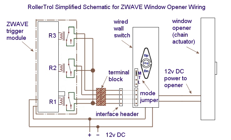
In the diagram below, we have added the wired wall switch and window opener to the wiring diagram. The dots on the wire path indicate spots where the wires are actually connected, and not just crossing each other.
You should be able to see where the 3 solid color wires from the bottom side of each relay connect together to form a common ground. When the relays close, the circuit to ground is closed, which is what activates the switch via the header.
In fact, these relays are actually connected in parallel with the push button switches on the wired wall switch, and the relays do exactly the same thing as if you had pressed one of the switch buttons - close the circuit to ground. This action activates a transistor circuit, which in turn controls the output of the switch accordingly, activating the window opener.You don't really need to understand this schematic to make it work; we have just included it in case you are interested in how it works. If you "just want it to work" you can simply follow the color coding of the wires and connect it as per the discussion and pictures further down on this page ...
Z-Wave Motor Control System for Window Openers: Wiring Pictures
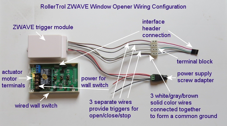
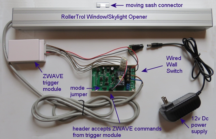
Power: The red and black ZWAVE module wires are for power (red: +12v and black: ground). Note that in the picture there is a second set of wires inserted into the screw adapter for the power supply.
This parallel connection will power the wired wall switch, so that both units share the same power supply. The current draw of the ZWAVE module is quite low (~25 ma), most of the power goes to the wired wall switch which then powers the actuator, which can draw up to 2 amps.
Switch Mode: The wired wall switch has 3 operating modes: momentary, latched, and toggle. The momentary mode should be used to avoid contact bounce issues (see mode jumper setting in picture above), and the zwave trigger relays should be set to hold the wall switch on for the duration of the window opener travel, typically around 30 seconds. The zwave trigger timing can be up to 255 seconds (about 4 minutes).
For more information about the wired wall switch, please see this article: how to use wired wall switch with DC blind motors
Here is the color coding of the 6 ZWAVE relay wires, connected to the wall switch header wires:
| ZWAVE Trigger Module Cable | Wired Wall Switch Header Cable |
|---|---|
| Relay 1 (open) | |
| solid white | solid white (common ground) |
| white with black stripe | solid green |
| Relay 2 (close) | |
| solid gray | solid white (common ground) |
| gray with black stripe | solid red |
| Relay 3 (stop) | |
| solid brown | solid white (common ground) |
| brown with red stripe | solid black |
Here is a picture of the wiring, somewhat spread out so you can see what goes where:
Here's a picture showing how the female header cable mates with the 4 pin male header on the wired wall switch board; we've added the actuator (window opener) and the power supply, which completes the package. This is what is in Window Opener Kit #1 (click to open in new window).
This system can control a group of window openers connected in parallel, up to the 10 amp capacity of the wall switch (about 4 or 5 actuators, depending on load), provided you upsize the power supply output capability accordingly. You could just as easily use this to control an unlimited group of our radio blind and shade motors (as per next article), or a group of our non-radio motors, or any other 12v DC device (LED strip lighting, fans, valves, etc).
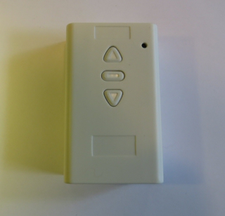
In the picture below, you can see what the wired wall switch looks like installed on a wall. Everything else from the picture above can be concealed, and you could also conceal the wall switch if you didn't care about controlling the window opener manually.
 In the next instalment, we'll show you how to connect the ZWAVE trigger device to the radio wall switches that provide control over our shade and blind motors, including our very popular remote control blind motors with a built-in battery (and 'in window' solar charging option).
PART 1: ZWAVE control of shade and blind motors - Introduction
PART 2: ZWAVE motor controller for blinds and window openers - Connecting to the wired wall switch (YOU ARE HERE)
PART 4: ZWAVE controller for blind motors- Creating ZWAVE controller events (Vera example)
We sincerely hope you enjoy using these advanced motors; if you have any questions, please feel free to contact us at any time!

 Shopping Cart Home - Start Here
 Remote Controls for Radio Equipped Motors
 DIY Starter Kits for Window Shades
 DIY Starter Kits for Window Openers
 ZWAVE Blind & Shade Controllers
 How To Choose the Right Blind & Shade Motor
 Select tubular Motor (Comparison table)
 Choose RollerTrol Battery & Solar Motors
 DIY Roller Blind Motors - FAQ
 How To Insert Blind Motors & Attach Brackets
 Calculate your Blind or Shade fabric Weight
 Select Tube Size for Blind Motor
 How to Insert Blind Motors Into Tube
 How to Insert Blind Motors Into Tube with Adapters
 Attach Mounting Brackets - Standard + Mini Series
 Attach Mounting Brackets - MAXI Blind Series
 How To Set Up Radio Equipped Blind & Shade Motors
 Series P Radio Remote Control Motors
 Series G Radio Remote Control Motors
 Series R Radio Remote Control Motors
 BroadLink RF/IR Hub System for Motors
 How To Set Up Window/Skylight Openers
 Introduction: Window & Skylight (K Series)
 BroadLink RF/IR Hub System for Motors
 Z-Wave Interfacing for Shade & Opener Motors
 Wired Wall Switch Control of Window Openers
 How To Use Alexa With Our Motors & Window Openers
 How To Use BroadLink Phone App Hub With Our Motors
 How To Set Up ShadeSlider Skylight or Bottom-Up Blind
 How To Retrofit RV, Boat and Motorhome Blinds
 How To Set Up Non-Radio Motors
 Operation & Travel Limits of Non-Radio Motors
 Make a Simple DC Motor Reversing Switch
 How To Set Up ZWAVE Control
 ZWAVE Controller for G Series Radio motors
 ZWAVE Door/Window Opening Detection
 ZWAVE Motion Detector with Temperature Sensing
 Motorized Window Blinds & Shades
 Motorized Dual Window Shade
 Make Motorized Blackout Blinds
 Phone-Tablet-PC Control for Motorized Blinds
 Mini Motor for Existing Shade Retrofit
 Roman Shade Retrofit
 Make a Motorized Window Opener
 Blind & Shade Motors for RV & Boats
 Make Your Own Projector Screen
 Curtain Closer: Ultimate Home Theater
 Wireless Battery Operated Drapery Motor Kit
 Make a Motorized Bottom-Up Shade
 Make a Motorized Skylight Opener
 BroadLink RF/IR Hub System for Motors
 Why Buy From US?
 Background & Mission Statement
 Customer DIY Testimonials
 Site Map - Search All Pages
 Why Buy From US?
 RollerTrol Users Forum
 Contact Page