
 Shopping Cart Home - Start Here
 Remote Controls for Radio Equipped Motors
 DIY Starter Kits for Window Shades
 DIY Starter Kits for Window Openers
 ZWAVE Blind & Shade Controllers
 How To Choose the Right Blind & Shade Motor
 Select tubular Motor (Comparison table)
 Choose RollerTrol Battery & Solar Motors
 DIY Roller Blind Motors - FAQ
 How To Insert Blind Motors & Attach Brackets
 Calculate your Blind or Shade fabric Weight
 Select Tube Size for Blind Motor
 How to Insert Blind Motors Into Tube
 How to Insert Blind Motors Into Tube with Adapters
 Attach Mounting Brackets - Standard + Mini Series
 Attach Mounting Brackets - MAXI Blind Series
 How To Set Up Radio Equipped Blind & Shade Motors
 Series P Radio Remote Control Motors
 Series G Radio Remote Control Motors
 Series R Radio Remote Control Motors
 BroadLink RF/IR Hub System for Motors
 How To Set Up Window/Skylight Openers
 Introduction: Window & Skylight (K Series)
 BroadLink RF/IR Hub System for Motors
 Z-Wave Interfacing for Shade & Opener Motors
 Wired Wall Switch Control of Window Openers
 How To Use Alexa With Our Motors & Window Openers
 How To Use BroadLink Phone App Hub With Our Motors
 How To Set Up ShadeSlider Skylight or Bottom-Up Blind
 How To Retrofit RV, Boat and Motorhome Blinds
 How To Set Up Non-Radio Motors
 Operation & Travel Limits of Non-Radio Motors
 Make a Simple DC Motor Reversing Switch
 How To Set Up ZWAVE Control
 ZWAVE Controller for G Series Radio motors
 ZWAVE Door/Window Opening Detection
 ZWAVE Motion Detector with Temperature Sensing
 Motorized Window Blinds & Shades
 Motorized Dual Window Shade
 Make Motorized Blackout Blinds
 Phone-Tablet-PC Control for Motorized Blinds
 Mini Motor for Existing Shade Retrofit
 Roman Shade Retrofit
 Make a Motorized Window Opener
 Blind & Shade Motors for RV & Boats
 Make Your Own Projector Screen
 Curtain Closer: Ultimate Home Theater
 Wireless Battery Operated Drapery Motor Kit
 Make a Motorized Bottom-Up Shade
 Make a Motorized Skylight Opener
 BroadLink RF/IR Hub System for Motors
 Why Buy From US?
 Background & Mission Statement
 Customer DIY Testimonials
 Site Map - Search All Pages
 Why Buy From US?
 RollerTrol Users Forum
 Contact Page
In part 2 we discussed the layout and controls of the MCS-1-RF wireless window mounted light sensor that can be used to activate our radio equipped blind and shade motors using RF (Radio Frequency). In part 3, we will see how to link the light sensor transmitter to the receiver of a radio motor (or several motors).
At this point the button battery should be inserted into the battery compartment, and the light sensor unit powered up. Please note that the + side of the battery should face up. The LED should flash if you press the Up/Down/Stop test button.
The 'confirm' switch behaves the same way as the switches of the same name on our regular remote controls.
1. Preparing the RollerTrol™ motor:
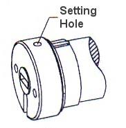
Figure 1: Set Program
Each RollerTrol™ motor has a a small hole on the outside edge of the cap at the wired end of the tubular motor. At the bottom of the hole is a small switch for activating the 'programming' mode of the motor.
You can feel a pronounced click when this switch is activated, when inserting a small screwdriver or similar item into the hole. You do not need to apply much pressure for this to be activated.
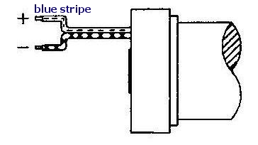
Figure 2: Wiring
Connect the motor to your power supply, then follow the instructions below to complete the programming.
A standard DC motor normally reverses direction when the polarity is reversed, but these units have special circuity that requires you observe the correct polarity.
Connect the wire with the blue stripe to the positive (+) power supply terminal.
If you are operating more than 1 motor from the same power supply, wire the motors in parallel: connect both positive leads together and both negative leads together.
Please note that you can control the direction of the motor by programming (see step 5 below), but it will not function if you connect the wires in reverse (they are reverse polarity protected, so you cannot damage the electronics if you accidently connect it in reverse).
2. Clearing the motor memory:
- Insert screwdriver into the setting hole and hold the setting switch down. After 3 seconds, you will hear a beeping sound.
- This will be the 'long beep' sound referred to in further instructions (beep ... beep ... beep).
- Continue to hold the switch down for a few more seconds, until you hear a series of short beeps.
- This will be the 'short beep' sound referred to in further instructions (beep.beep.beep).
- After you hear the short beeps, the memory clearing procedure is complete and you can release the switch. However, It is a good idea to continue to hold the setting switch down until you have heard two complete cycles of beeps (or the beeping stops), then you know for sure the unit has cleared its memory.
The operation is done at this point - the memory has been cleared. You can reset the memory as many times as you like.
3. Linking the Motor to the Light Sensor:
- Insert the screwdriver into the motor 'programming' hole and hold the switch down for about 3 seconds. When you hear the long beeps (beep ... beep ... beep), release the screwdriver. The motor is now in programming mode and is waiting for its channel assignment.
- To complete the channel assignment, press and release the 'confirm' button on the light sensor (see picture above). You will hear a series of short beeps almost immediately.
At this point, the operation is complete - the motor is linked to the light sensor. You should be able to activate the motor by pressing the Up/Down/Stop test button on the light sensor. The sequence is Roller UP (red LED), Roller STOP (red + green LED), Roller DOWN (green LED), Roller STOP (red + green LED). If the motor fails to rotate, it probably means you have reached the travel limit in one direction, so try reversing it.
PLEASE NOTE: The following operations - motor reversal and travel limits - must be done with a standard remote control or timer unit, the light sensor will NOT perform these functions!
4. Testing the Motor Direction:
You should be able to run the motor at this point as described above. If the motor runs in the opposite direction to the one desired, you can reverse the motor direction. This will change what happens with the blind when it reaches the strong or weak light thresholds. You may want the blind to open at dawn and close at dusk, or you may prefer to have it close if the sun is too bright.
- hold down the 'limit' switch, then hold down the stop button also (holding down both at the same time).
- after a few seconds, you will hear the short beeps (beep.beep.beep) and the transmit symbol on the remote control or timer will be activated
- release both buttons and test the motor again with the Up/Down buttons (it should now run in the opposite direction).
Please Note: If you accidentally hold down the Confirm button, instead of the Limit button: This puts it into the travel limit setting mode, and you have to complete the operation before you can go back to the reversal programming. You can tell if you're in that mode because the motor will 'jog' in small steps in one direction or the other, so that you can accurately set the travel limits. You have to complete both up and down travel limit settings before you can get out of that mode (see step 4).
You can also link more than one motor (as many as you like) to the remote control or timer simply by following the same procedure above. Note that when you get to the point of setting the travel limits, it is a good idea to make sure only the motor you wish to program is powered up, otherwise you will be setting the travel limits simultaneously for all motors. This can be problematic because it is unlikely they are all starting from the same point.
4. Setting the Upper and Lower Travel Limits:
The travel limits of a RollerTrol™ motor can be set and changed at any time with the remote control or timer (make sure it is not in AUTO timed mode); you do not have to touch the motor at all. The sequence is as follows:
Setting the Upper Limit:
- Press and hold down the 'Limit' button (figure 4) for 3 seconds, until you hear the 3 'long beeps'. This action places the motor into its limit programming mode.
- Press the UP button on the remote; the motor will move in the up direction at normal speed.
- When it gets close to the upper limit, press the STOP button. The motor now enters the 'Jog' mode.
- Press the UP or DOWN buttons to move the motor slightly in one direction or the other. You'll see the motor move in very short steps that are a small fraction of a full rotation. Use this mode to position your motor at the exact upper limit you desire.
- Press the 'Confirm' button. After you hear the 3 'short beeps', the upper limit has been set. The motor is still in 'programming mode' so that you can set the lower limit.
Setting the Lower Limit:
- Press the DOWN button on the remote; the motor will move in the down direction at normal speed.
- When it gets close to the lower limit, press the STOP button. The motor now enters the 'Jog' mode.
- Press the UP or DOWN buttons to move the motor slightly in one direction or the other. You'll see the motor move in very short steps that are a small fraction of a full rotation. Use this mode to position your motor at the exact lower limit you desire.
- Press the 'Confirm' button. After you hear the 3 'short beeps', the upper limit has been set. The motor is now back in normal running mode and you should be able to test the full excursion.
5. Repeat the above steps for each motor:
The process is the same for all motors in the group, but it is a good idea to make sure only the motor you wish to program is powered up, otherwise you will be setting the travel limits simultaneously for all motors. This can be problematic because it is unlikely they are all starting from the same point.
PART 1: Sunlight sensor for blinds - Removing the Cover
PART 2: Sunlight sensor for blinds - Controls and Layout
PART 3: Sunlight sensor for blinds - Linking to a Radio Motor
PART 4: Sunlight sensor for blinds - Adjusting Light Sensing Modes
We sincerely hope you enjoy using these advanced motors; if you have any questions, please feel free to contact us at any time!